

| Power Supply: 13,8 V | Frequency Counter | Dummy Load 50 ohm | Oscilloscope |
| DC Amperemeter | RF SSG | AF SSG |
| Clarifier | Mid. |
| SQ GAIN | Max. |
| AF GAIN | Max. |
| RF GAIN | Max. |
| MIC GAIN | Max. |
| MOD, S/RF | S/RF |
| NB/ANL | Off |
| Channel | 19 |
| Item | Setting | Adjust | Measurement |
|---|---|---|---|
| PLL ALIGNMENT | |||
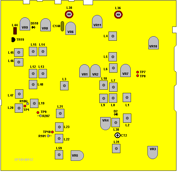
| VCO Voltage | Set radio to CH 1, AM RX mode. Clarify setting in 12 o’clock position. Connect DC Voltmeter to TP9 (R207). Connect Oscilloscope to TP10 (R101). Connect Oscilloscope to TP1 (R106). | L19 L21 L20 | 2.5 VDC ± 0.1 CH 1 & CH 40 Max. Output and Balance. |
| AM Frequency | Set radio to CH 1, AM RX mode. Connect frequency counter to TP1 (R106). | L23 | 34.76500 MHz ± 20 Hz |
| LSB Frequency | Set radio to CH 1, LSB RX mode. Connect frequency counter to TP1 (R106). | L22 | 34.76350 MHz ± 20 Hz |
| USB Frequency | Set radio to CH 1, USB RX mode. Connect frequency counter to TP1 (R106). | L59 | 34.76650 MHz ± 20 Hz |
| TX Frequency | Set radio to CH 1, AM TX mode. Connect frequency counter to TP1 (R106). | VR5 | 34.76500 MHz ± 20 Hz |
| AM TX Frequency | Set radio to CH 19, AM TX mode. Set Mic Gain fully counter clockwise. | L31 | 27.18500 MHz ± 20 Hz |
| LSB TX Frequency | Set radio to CH19, LSB TX mode. Set Mic Gain fully clockwise. AF signal 25 mV, 1 KHz to microphone. | L30 | 27.18400 MHz ± 20 Hz |
| USB TX Frequency | Set radio to CH19, USB TX mode. Set Mic Gain fully clockwise. AF signal 25 mV, 1 KHz to microphone. | CT2 | 27.18600 MHz ± 20 Hz |
| TRANSMITTER ALIGNMENT | |||
| BIAS Current | Set radio to CH 19, USB TX mode. MOD off. Connect current meter to TP8 (+) and green lead wire (-). Connect current meter to TP7 (+) and violet lead wire (-). | VR8 VR9 | 30mA 50mA |
| AM TX Power | Set radio to CH 19, AM TX mode. Connect RF power meter to antenna jack. | L48, L47 L46, L45 L38, L36 L38 VR10 | RF Power Output MAX Balance Power between CH 1 and CH 40. 4W. |
| SSB ALC | Set radio to CH 19, USB TX mode. Set Mic Gain fully clockwise. AF signal 25 mV, 1 KHz to microphone. | VR11 | 12W |
| SSB Carrier Balance | Set radio to CH 19, USB TX mode. Connect Oscilloscope to L44 (TR39C). Mic Gain off. | VR4 | Spurious Emission to minimum. |
| AM Modulation | Set radio to CH 19, AM TX mode. Set Mic Gain fully clockwise. AF signal 30 mV, 1 KHz to microphone. | VR7 | 90% |
| RF Power Meter | Set radio to CH 19, AM TX mode. MOD off. | VR6 | Adjust RF Power meter needle until it is in-between the green and red bar on PWR scale. |
| RECEIVER ALIGNMENT | |||
| AM Sensitivity | Set radio to CH 20, AM RX MODE. Clarify setting in 12 o’clock. Set RF gain fully clockwise. Set SQ fully counter clockwise. Set VOL control to 2 o’clock. Set NB/ANL to OFF position. Connect RF SG to antenna jack. Frequency 27.205 MHz, Level 1 uV. MOD 30%, 1KHz. Set radio to CH 40 AM mode. RF SG setting 27.405 MHz. Set radio to CH 1 AM mode. RF SG setting 26.965 MHz. | L13, L15 L3, L4, L5 L6, L7, L8 L9, L10 |
Audio output > 2V S/N > 10 dB |
| USB Sensitivity | Set radio to CH 20, USB RX mode. MOD off. Set VOL control fully clockwise. RF SG setting 27.206 MHz, Level 1 uV. | L12, L14 | Audio output > 4.5V S/N > 20 dB |
| LSB Sensitivity | Set radio to CH 20, LSB RX mode. MOD off. VOL control fully clockwise. RF SG setting 27.204 MHz, Level 1 uV. | L12, L14 | Audio output > 4.5V S/N > 20 dB |
| NB/ANL Adjust | Set radio to CH 20, AM RX mode. RF SG setting 27.205 MHz, Level 100 uV. MOD 30%, 1KHz. Set NB/ANL/OFF switch to NB/ANL. Connect Voltmeter to D2 (Cathode). | L1, L2 | DC voltage to max. ( >1.5V ) |
| AM Squelch | Set radio to CH 20, AM RX mode. Set SQ control at fully clockwise. RF SG setting 27.205 MHz, Level 1 mV. MOD 30%, 1KHz. | VR3 Slowly | Adjust very slowly until quelch just open |
| AM S/RF Meter | Set radio to CH 20 AM RX mode. MOD off. Set S-RF/CAL/SWR switch to S/RF position. RF SG setting 27.205 MHz, Level 100 uV. | VR1 | Meter needle to S9 on the S scale |
| SSB S/RF Meter | Set radio to CH 20, USB RX mode. MOD off. Set S-RF/CAL/SWR switch to S/RF position. RF SG setting 27.206 MHz, Level 100 uV | VR2 | Meter needle to S9 on the S scale |
| Pin | Description |
|---|---|
| 1 | Microphone Ground |
| 2 | Microphone |
| 3 | RX Key (Connect to Ground) |
| 4 | Ground |
| 5 | TX Key (Connect to Ground) |