

Funtions:
Frequency range from 26,510MHz to 30,415MHz in 5kHz step
Step Up and Step Down
Scan Up and Scan Down
Dual Watch
Repeater function (Split)
2 Memory Bank with 100 memories
System Requirements:
IBM PC compatible
Windows 16/32 bit and Windows NT operating system
1 MB of RAM, 1 MB of free disk space
PTBM133 Software
CB-Radio with PTBM133A4X Board
Price:
Few component`s
1 pcs. 25-Pin D-SUB Connector
1 pcs. NULL-Modem Cable
The connection to Printer port.

Install a 25-pin D-SUB Male connector on the radio`s bottom cover, and use
a NullModem cable to the computer`s printer port.
See Radio interfacing to Printer Port for more
information about using PrinterPort.
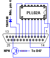
| Pin | PrinterPort | Direction | Usage | Connection to: | Active H/L |
|---|---|---|---|---|---|
| 1 | Data 8 | Out to radio | PLL02A pin 7 | HIGH | |
| 2 | Data 0 | Out to radio | PLL02A pin 15 | HIGH | |
| 3 | Data 1 | Out to radio | PLL02A pin 14 | HIGH | |
| 4 | Data 2 | Out to radio | PLL02A pin 13 | HIGH | |
| 5 | Data 3 | Out to radio | PLL02A pin 12 | HIGH | |
| 6 | Data 4 | Out to radio | PLL02A pin 11 | HIGH | |
| 7 | Data 5 | Out to radio | PLL02A pin 10 | HIGH | |
| 8 | Data 6 | Out to radio | PLL02A pin 9 | HIGH | |
| 9 | Data 7 | Out to radio | PLL02A pin 8 | HIGH | |
| 10 | ACK | In from radio | PTT Switch | Microphone connector Pin 4 | LOW |
| 11 | Busy | In from radio | Squelch Control | Souelch sircuit | LOW |
| 18 | Ground | Ground | PLL02A pin 16 |
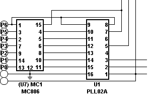
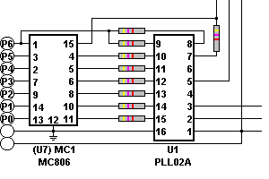
| Before modification | After modification |
|---|---|
 To protect the PrinterPort: Cut the trace between U7 (MC806)and U1 |
 and insert 9 pcs. 4,7kW resistors across the cutted traces. |
| Connection to the PrinterPort | Squelch sircuit |
|---|---|
 |
To use the Scan function you will need a Squelch sircuit. Use a BC107 or similar NPN Transistor (Not critical) and a 4,7kW resistor and connect it to D47 Anode. Use also a 1N4148 or similar diode to protect the input fron the PTT-Switch. |
Software: