


Functions:
Frequency range from 24,255MHz to 29,365MHz
5kHz and 10kHz Frequency Step
Step Up and Step Down
Scan Up and Scan Down
Dual Watch
Repeater function (Split)
2 Memory Bank with 100 memories
System Requirements:
IBM PC compatible
Windows 16/32 bit and Windows NT operating system
1 MB of RAM, 1 MB of free disk space
EPT3600 Software
Connex CX-4400 CB-Radio
Price:
Few component`s
1 pcs. 25-Pin D-SUB Connector
1 pcs. NULL-Modem Cable
The connection to Printer port.

Install a 25-pin D-SUB Male connector on the radio`s bottom cover, and use
a NullModem cable to the computer`s printer port.
See Radio interfacing to Printer Port for more
information about using PrinterPort.
| Pin | PrinterPort | Direction | Usage | Connection to: | Active H/L |
|---|---|---|---|---|---|
| 1 | Data 8 | Out to radio | MC145106 pin 9 | HIGH | |
| 2 | Data 0 | Out to radio | MC145106 pin 17 | HIGH | |
| 3 | Data 1 | Out to radio | MC145106 pin 16 | HIGH | |
| 4 | Data 2 | Out to radio | MC145106 pin 15 | HIGH | |
| 5 | Data 3 | Out to radio | MC145106 pin 14 | HIGH | |
| 6 | Data 4 | Out to radio | MC145106 pin 13 | HIGH | |
| 7 | Data 5 | Out to radio | MC145106 pin 12 | HIGH | |
| 8 | Data 6 | Out to radio | MC145106 pin 11 | HIGH | |
| 9 | Data 7 | Out to radio | MC145106 pin 10 | HIGH | |
| 10 | ACK | In from radio | PTT Switch | Microphone connector Pin 3 | LOW |
| 11 | Busy | In from radio | Squelch Control | Squelch sircuit, IC1 pin 8 | LOW |
| 14 | Strobe | Out to radio | Frequency select | MC145106 pin 6 | 10kHz = Low and 5kHz = High |
| 18 | Ground | Ground | MC145106 pin 18 |
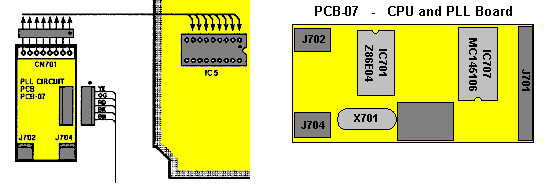
| Before modification | After modification |
|---|---|
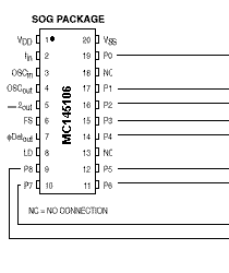 To protect the PrinterPort: Cut the trace between MC145106 on PLL-PCB.... |
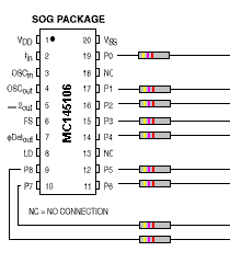 and insert 9 pcs. 4,7kW resistors across the cutted traces. |
| Connection to the PrinterPort | Squelch and PTT circuit |
|---|---|
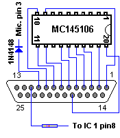 |
Connect a 4,7kW resistor to the SQ-circuit. Use also a 1N4148 or similar diode to protect the input fron the PTT-Switch. Connect a wire from PrinterPort pin 14 to MC145106 pin 6 to obtain 5kHz and 10kHz frequency Step. |
Setup
The off-set-frequency oscillator IC10 oscillates at:
13.560MHz
for all band.
The off-set frequency signal is obtained at IC10 Oscillator and flows into IC10 Mixer
where it is beat with the VCO signal. The VCO signal is obtained from the following:
fvco = foff-set + Nfr
Where:
f vco = VCO frequency
N = programming code for divider output
fr = referency frequency step (10kHz).
When the different radio`s use different off-set X-tals, go to SETUP
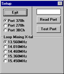
and select off-set X-tal.
Software: