


| Pin | PrinterPort | Direction | Usage | Connection to: | Active H/L |
|---|---|---|---|---|---|
| 1 | Data 8 | Out to radio | MC145106 pin 9 | HIGH | |
| 2 | Data 0 | Out to radio | MC145106 pin 19 | HIGH | |
| 3 | Data 1 | Out to radio | MC145106 pin 17 | HIGH | |
| 4 | Data 2 | Out to radio | MC145106 pin 16 | HIGH | |
| 5 | Data 3 | Out to radio | MC145106 pin 15 | HIGH | |
| 6 | Data 4 | Out to radio | MC145106 pin 14 | HIGH | |
| 7 | Data 5 | Out to radio | MC145106 pin 12 | HIGH | |
| 8 | Data 6 | Out to radio | MC145106 pin 11 | HIGH | |
| 9 | Data 7 | Out to radio | MC145106 pin 10 | HIGH | |
| 10 | ACK | In from radio | PTT Switch | Microphone connector Pin 3 | LOW |
| 11 | Busy | In from radio | Squelch Control | Souelch sircuit, IC1 pin 8 | LOW |
| 18 | Ground | Ground | MC145106 pin 20 |
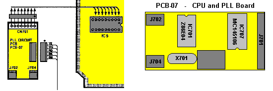
| Before modification | After modification |
|---|---|
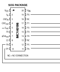 To protect the PrinterPort: Cut the trace between IC706 and IC707 on the CPU- and PLL-board.... |
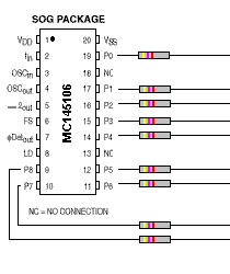 and insert 9 pcs. 4,7kW resistors across the cutted traces. |
| Connection to the PrinterPort | Squelch and PTT circuit |
|---|---|
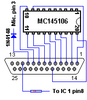 |
Connect a 4,7kW resistor to the SQ-circuit. Use also a 1N4148 or similar diode to protect the input fron the PTT-Switch. |
|
|