

| Pin | PrinterPort | Direction | Usage | Connection to: | Active H/L |
|---|---|---|---|---|---|
| 2 | Data 0 | Out to radio | PLL Clock | U101 Pin 9 | HIGH |
| 3 | Data 1 | Out to radio | PLL Data | U101 Pin 10 | HIGH |
| 4 | Data 2 | Out to radio | PLL Enable | U101 Pin 11 | HIGH |
| 5 | Data 3 | Out | Trig to Oscilloscoope | Not in use | HIGH |
| 8 | Data 6 | Out to radio | Audio Mute | HIGH | |
| 9 | Data 7 | Out to radio | Reset to A/D | A/D-Converter | HIGH |
| 10 | ACK | In from radio | PTT Switch | LOW | |
| 11 | Busy | In from radio | Squelch Control | HIGH | |
| 12 | PaperEnd | In from radio | A/D output | A/D-Converter | LOW |
| 18 | Ground | Ground | U101 Pin 6 |
| Modification | |
|---|---|
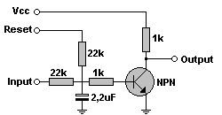
 | You have to do some small modification around the MC145157 PLL-Circuit (U101). Cut the traces to Data, CLK and ENB inputs on the PLL and insert 3 pcs. 4,7kW resistors across the cutted traces. This is to protect the CPU from be destroyed when the radio is connected to the PC printerport. This is a simple ADC for reading the S-meter value. Connect the S-Meter signal to the Input, and the Output to the PaperEnd signal and Reset to Data 7 on the printerport. Use a BC107 or similar NPN Transistor (Not critical). |