![]()
![]()
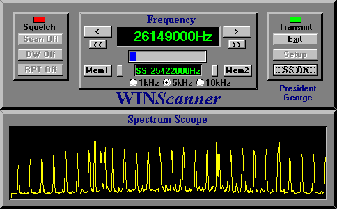
Functions:
Frequency range from 25MHz to 31MHz (Without modification)
Select Step between 1kHz, 5kHz and 10kHz
Step Up and Step Down
Scan Up and Scan Down
Dual Watch
Repeater function (Split)
2 Memory Bank with 100 memories
Signal Meter
1MHz Spectrum Scoope
System Requirements:
IBM PC compatible
Windows 16/32 bit and Windows NT operating system
1 MB of RAM, 1 MB of free disk space
WINGeorge Software
President George CB-Radio
Price:
Few components
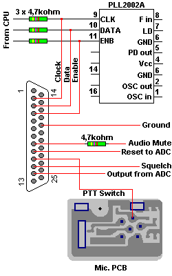
1 pcs. 25-Pin D-SUB Connector
1 pcs. NULL-Modem Cable
The connection to Printer port.
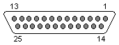
Install a 25-pin D-SUB Male connector on the President George bottom
cover, and use a NullModem cable to the computers printer port.
See Radio interfacing to Printer Port for more
information about using PrinterPort.
| Pin | PrinterPort | Direction | Usage | Connection to: | Active H/L |
|---|---|---|---|---|---|
| 2 | Data 0 | Out to radio | PLL Clock | IC401 Pin 9 | HIGH |
| 3 | Data 1 | Out to radio | PLL Data | IC401 Pin 10 | HIGH |
| 4 | Data 2 | Out to radio | PLL Enable | IC401 Pin 11 | HIGH |
| 5 | Data 3 | Out | Trig to Oscilloscope | Not in use | HIGH |
| 8 | Data 6 | Out to radio | Audio Mute | IC404 Pin 10 | HIGH |
| 9 | Data 7 | Out to radio | Reset to A/D | A/D-Converter | HIGH |
| 10 | ACK | In from radio | PTT Switch | Microphone PCB Pin 3 | LOW |
| 11 | Busy | In from radio | Squelch Control | IC2 Pin 7 | HIGH |
| 12 | PaperEnd | In from radio | A/D output | A/D-Converter | LOW |
| 18 | Ground | Ground | IC401 Pin 6 |
| Modification | |
|---|---|
 |
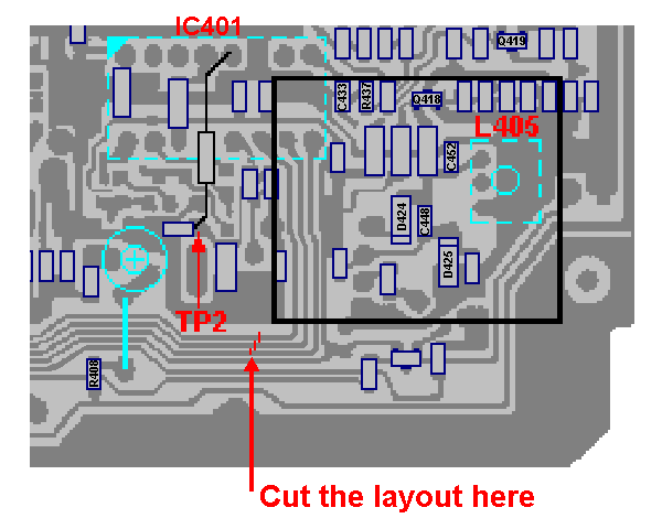
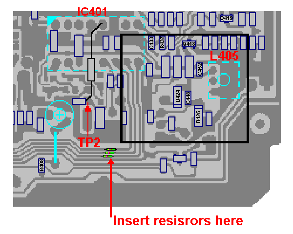
You have to do some small modification around the PLL2002A PLL-Circuit (IC401). Cut the traces to Data, CLK
and ENB inputs on the PLL and insert 3 pcs. 4,7kW resistors
across the cutted traces. This is to protect the CPU from be destroyed when the radio is
connected to the PC printerport. |
| Cut the trace.... | ... and insert 3 pcs. resistors. |
|---|---|
|
|
PLL Carrier Oscillator Portion
| Condition | Adjustment | Procedure |
|---|---|---|
| RX AM 27.405 MHz |
L405 | Connect the DC Voltmeter to TP2 Adjust for 1.5 +/- 0.1 V |
Frequency range
The frequency range is set to 25MHz to 30MHz because the this is the limit for the
receiver BandPassFilter FL401.
When you first time start up the WINGeorge software, its will create 3 files;
Setup.TXT
Memory1.TXT and
Memory2.TXT.
In the file Setup.TXT you will find the that the 2 last lines is the Minimum and Maximum
frequency for the software.
25000500
888
889
10000
27555000
25000000
31000000
You can change this values for the software. If you want to set the Maximum or Minimum
frequencies outside the limit for the receiver BandPassFilter, you have to re-tune this
filter for the new frequencies. It will also be necessary to modificate the VCO-circuit,
take a look at How to change the frequency band for the VCO-circuit.
Software:
 To use the Spectrum Scoope you
will need a AnalogDigitalConverter.
To use the Spectrum Scoope you
will need a AnalogDigitalConverter.