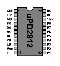
| Pin | Name | Decription |
|---|
| 1 | GND | Ground |
| 2 | FIN | VCO Oscillator Input |
| 3 | MS | Mode Select - HIGH=40 Channels ROM - LOW=Binary input (N=3-255) |
| 4 | PO | Programable Divider Output |
| 5 | DO | Reference Divider Output |
| 6 | AO | Loop filter Amplifier Output |
| 7 | AI | Loop filter Amplifier Input |
| 8 | PD | Phase Detector output |
| 9 | LD | Loop Detector output - Locked=HIGH Unlocked=LOW |
| 10 | VDD | Positive Power Supply (+5Volt) |
| 11 | I | Inhibit |
| 12 | P1 | Binary programable input 1 |
| 13 | P2 | Binary programable input 2 |
| 14 | P3 | Binary programable input 3 |
| 15 | P4 | Binary programable input 4 |
| 16 | P5 | Binary programable input 5 |
| 17 | P6 | Binary programable input 6 |
| 18 | P7 | Binary programable input 7 |
| 19 | P8 | Binary programable input 8 |
| 20 | 1/2R | Referency frequency divided by 2 |
| 21 | RI | Referency oscillator Input (X-tal) |
| 22 | RO | Refeerency oscillator Output (X-tal) |


