| Power Supply: 13,8 V | Oscilloscope | Frequency Counter | DC Voltmeter |
| PA SW | Off | ||
| RIT | Middle position | ||
| Mode | AM | ||
| Frequency | 28.000 MHz |
| Step | Condition | Adjustment | Procedure |
|---|---|---|---|
| 1 | AM RX | L315 | Connect the Oscilloscope and Frequency Counter to TP306. Adjust for 6.200 MHz +/- 20 Hz |
| 2 | AM RX | L318 | Connect the Oscilloscope and Frequency Counter to TP304. Adjust for 38.6950 MHz +/- 20 Hz. Check: USB : 38.6975MHz LSB : 38.6925MHz |
| 3 | AM RX | L317 | Connect the DC Voltmeter to TP 303. Adjust for 6.5 V +/- 0.1 V |
| 4 | CW RX | L117 | Connect the Oscilloscope and Frequency Counter to TP1. Adjust for 10.695 MHz +/- 20 Hz |
| 5 | LSB RX | L118 | Connect the Oscilloscope and Frequency Counter to TP1. Adjust for 10.6925 MHz -40 Hz to + 0 Hz |
| 6 | USB RX | L116 | Connect the Oscilloscope and Frequency Counter to TP1. Adjust for 10.6975 +/- 20 Hz |
| 7 | USB RX | VR111 | Connect the Oscilloscope and Frequency Counter to TP5. Adjust for 38.6975 +/- 20 Hz |
| Adjustment | Description |
|---|---|
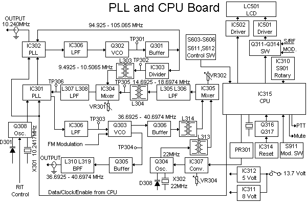
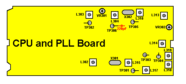
| VR304 | Amplifier Gain Adjustment |
| Only in President HR2600 | |
| Adjustment | Description |
|---|---|
| VR301 | DC Balance Adjustment for Balanced Mixer |
| L303 | 9-10MHz Signal Balance Adjustment to Mixer |
| L304 | 14-18MHz Signal Balance Adjustment to Mixer |
| Connect Oscilloscope to IC304 pin 2. Adjust VR301 for correct DC-balance. Adjust L303 for maximum signal. Adjust L304 for maximum signal. |
| Adjustment | Description |
|---|---|
| VR302 | DC Balance Adjustment for Balanced Mixer |
| L313 | 22MHz Signal Balance Adjustment to Mixer |
| L314 | 36-40MHz Signal Balance Adjustment to Mixer |
| Connect Oscilloscope to IC305 pin 2. Adjust VR302 for correct DC-balance. Adjust L313 for maximum signal. Adjust L314 for maximum signal. |
| Adjustment | Description |
|---|---|
| L310 | High Band Adjustment |
| L319 | Low Band Adjustment |
| Connect Oscilloscope to Output Terminal for VCO. Adjust L310 for maximum at 29.000MHz. Adjust L319 for maximum at 28.500MHz. |
| Band | Frequency Range (Without ChipSwitch or Frequency Modification) |
|---|---|
| A | 28.000 to 28.4999 MHz |
| B | 28.500 to 28.999 MHz |
| C | 29.000 to 29.4999 MHz |
| D | 29.5000 to 29.699 MHz |