
| Power Supply: 13,8 V | Frequency Counter | DC Voltmeter | Oscilloscope |
| RF SSG | 8 ohm DUMMY LOAD |
| Step | Condition | Adjustment | Procedure |
|---|---|---|---|
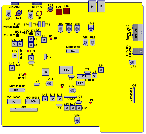
| 1 | Band C, Channel 19 NB/ANL Off MOD, S/RF: Off PA/SQL: SQL Clarifier: Center RF Gain: Max. AF Vol.: Max. MODE: AM | Set RF SSG to 27.185MHz with 30%, 1kHz modulation. | |
| 2 | Same as STEP 1 | L6 | Turn the core of L8 to ClockWise maximum at the bottom. |
| 3 | Same as STEP 1 | L5 L7 L8 L9 | Adjust coils for maximum reading on oscilloscope |
| 4 | Same as STEP 1 Except Band C, Channel 1 |
L6 | Set RF SSG to 26.965MHz. Adjust for maximum reading on oscilloscope. Then turn 1/4 turn AntiClockWise. |
| 5 | Same as STEP 1 | VR1 | Set the RF SSG to 100uV output with no modulation. Adjust VR1 to obtain "S-9" on transceiver`s meter. |
| 6 | Same as STEP 1 | VR2 | Adjust VR2 to turn off the squelch circuit when RF SSG RF output comes up to 1000uV |
| 7 | Same as STEP 1 Except MODE: USB |
L3 | Set RF SSG to 5uV. Connect oscilloscope to TP-1 (D2) so that adjust for maximum reading. |
| 8 | Same as STEP 1 Except MODE: FM |
L4 | Set the RF SSG to FM, 1kHz, 1.5kHz deviation, 1 mV output. Adjust L4 to obtain the maximum indication on oscilloscope |
