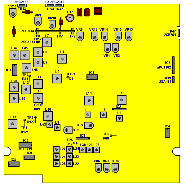
President Grant CB-Radio
President Grant "Classic" (Grey face, Dual 2312 finals, No ASC, PC999AE board)
Remove white wire from pin foil side of the PLL. Connect cut trace.
Remove second white wire on foil side towards the front of the radio (only other white wire).
Find purple wire behind ABC band switch. This wire is 3 inches long and has an open end with a piece of clear tubing over the end. Connect this wire to board ground. A good place is on the foil side where you took the second white wire off. The spot closest to the front edge is ground.
That’s it! You now have three bands of 40CH's.
Optional
Retune rear slug for max peak power on CH 20. This slug has white wax on the top. It is tuned for 28MHz. Typical 5 watt pep improvement and balanced RF power output across bands.
Improved receive gain
Quieting of AM and SSB reception and improving gain of incoming signals is a common request from radio operators.
In the first stages of the HF input 2SC1674 transistor can be found. This transistor is responsible for the amplification of a small detected signals. A problems exist if the transistor itself is noisy as is such the case of the 2SC1674 when compared to other low noise packages. Along with the amplification of the incoming signals is transistor noise. Replacement of this transistor with a higher gain, lower noise transistor greatly improves the signal to noise ratio of your receiver.
We will use an 2SC2999 transistor that has higher gain lower noise characteristic. Replace the 2SC1674 (TR17) with an
2SC2999 (or similar low noise and high gain transistor) to achieve this improved signal to noise ratio.
Re-adjust L7 and L8
The gain will improved with more than 6dB with the same signal to noise ratio.


CB Radio Banner Exchange


