
| Power Supply: 13,8 V | RF Signal Generator | Dummy Load 8 ohm | Oscilloscope |
| AF VTVM |
| Clarifier | Mid. |
| SQ GAIN | Max. |
| AF GAIN | Max. |
| RF GAIN | Max. |
| MIC GAIN | Max. |
| MOD, S/RF | S/RF |
| NB/ANL | Off |
| RF SSG | Modulation: 30% AM 1000Hz |
| Step | Condition | Adjustment | Procedure |
|---|---|---|---|
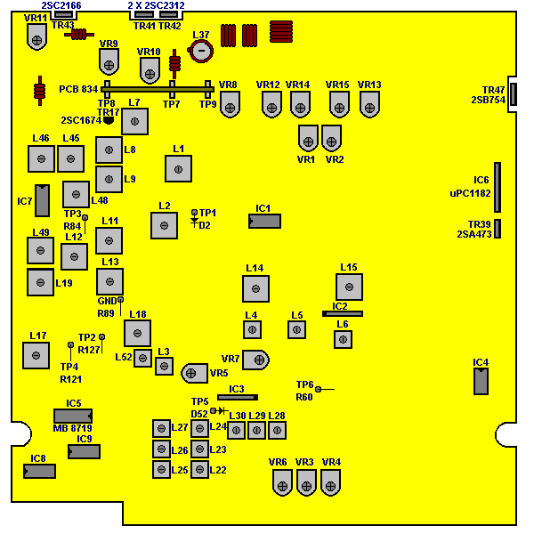
| 1 | Mode: RX AM Band: Mid. Channel: 19 | L8 | Set RF SSG on 27.185MHz, 1kHz 30% AM-mod. Adjust L8 for maximum reading on oscilloscope. |
| 2 | Same as STEP 1 | L7 L9 L11 L12 L13 L52 L3 L4 L5 | Adjust level of RF SSG to obtain 2V on AF VTVM then adjust coils for maximum reading on meter. |
| 3 | Same as STEP 1 | L8 | Adjust to obtain minimum difference between Ch. 40 and Ch. 1 |
| 4 | Same as STEP 1 | VR1 | Set the level of RF SSG to 100mV. Adjust VR1 for "5-9" reading on tranceiver meter. |
| 5 | Same as STEP 1 | VR4 | Set SQ on max. Adjust level of RF SSG to 1000mV, adjust VR4 so that the radio signal will apper on tranceiver. Set SQ on minimum. |
| 6 | Same as STEP 1 Mode: USB | L14 L15 | Set RF SSG on 27.186MHz. Adjust coils to obtain maximum reading on oscilloscope. |
| 7 | Same as STEP 1 | VR2 | Set level of RF SSG to 100uV. Adjust VR2 to obtain "S9" on transmitter meter. |
| 8 | Same as STEP 1 SQ: Max. | VR3 | Set level of RF SSG to 1000mV. Adjust VR3 so that the audio signal will apper on tranceiver |
| 9 | Same as STEP 1 NB/ANL: ON MID, Ch.18, USB | L1 L2 | Set RF SSG on 27.185MHz, 0% Mod., 10uV Level. Connect oscilloscope on D2 and adjust the coils to obtain maximum deviation. |
| 10 | Same as STEP 1 | L6 | Set RF SSG on 27.185MHz with 1 kHz deviation, 1000mV Level. Adjust L6 to obtain maximum. |
