![]()
![]()
| Pin | Description |
|---|---|
| 1 | Ground |
| 2 | Microphone |
| 3 | TX Key (Connect to Ground) |
| 4 | Speaker (Connect to Ground) |
Locate the small board (PCBX-9710) that has the channel selector attached to it. On the
right rear corner of this small board locate the small wire loop and cut it open. This is
about 3/16 of an inch loop. Open, or cut this wire loop, right against the board.
Now locate the "YELLOW" wire that comes from the edge connector of this same
little board that has the Channel selector. It runs over to the Bright/Dim switch. Some
Place in the middle of this wire you will see a black heat shrink tubing over the wire.
You must cut away that tubing, and reconnect the yellow wire, as it is an open connection
under that heat shrink.
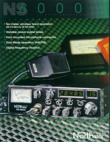
To select a band, you must place the dim switch all the way to DIM. This will now display
a n1, n2, n3.... n8 in the channel selector window. The CB Band is band 5 for most NS
series, except the NS-3000. Which is band 4.
Once you have selected the band you want, place Bright/DIM switch back to bright. You are
now on that band of operation.
NS-6000 Schematic Diagram
MC145106P PLL Frequency Synthesizer
TA7310 Oscillator, Mixer and Amplifier
NJM4558 Dual Operational Amplifier
TA6324 Quad Operational Amplifier