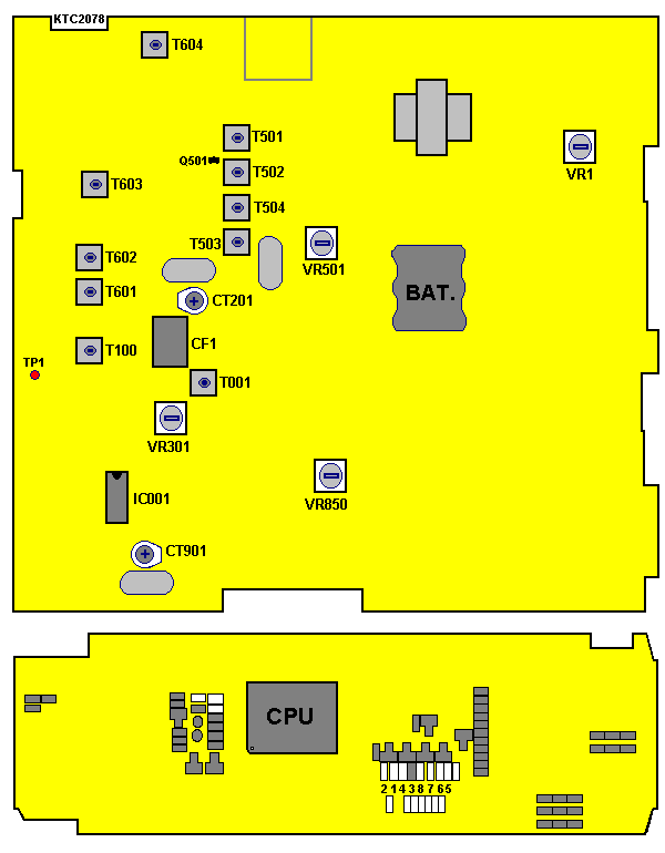

| Power Supply: 13,2 V | RF Power Meter | Oscilloscope | Audio Generator |
| Frequency Counter | Spectrum Analyzer | 50 ohm Load |
| Step | Setting | Connection | Adjust | Adjust for |
|---|---|---|---|---|
| 1 | RF Driver stage Mode: Transmit Volume: Optional Squelch: Optional Channel: 19 | Connect Oscilloscope to base of Q602 | T601 T602 | Adjust for maximum wave-form on the oscilloscope |
| 2 | RF Power stage Mode: Transmit Volume: Optional Squelsch: Optional Channel: 19 | Connect dummy-load and RF Power-meter to external ANT-jack | T604 | Adjust for maximum indication on the RF Power-meter |
| 3 | Second harmonic check Volume: Optional Squelch: Optional Channel: 19 | Connect RF Power-meter with dummy-load to spectrum analyzer | At no modulation compare the level of fundamental freq-spectrum to the level of harmonic freq-spectrum. Supression of the 2nd harmonic freq. level must be lower than -54dBm. | |
| 4 | Frequency check Mode: Transmit Volume: Optional Squelch: Optional Channel: 19 | Connect dummy-load and Frequency-counter to ANT-jack. | CT901 | Make sure that the indication of the transmit frequency is 27.185 MHz +/- 300 Hz. |
| 5 | Max. modulation check Mode: Transmit AM Volume: Optional Squelch: Optional Channel: 19 | Connect dummy-load and Modulation-meter to ANT-jack. | VR401 | Adjust so that the indication of the Modulation-analyzer is 90% with +/- 5% tolerance at high power mode. |
| 6 | Max. deviation check Mode: Transmit FM Volume: Optional Squelch: Optional Channel: 19 | Connect dummy-load and Modulation-meter to ANT-jack. | VR401 | Adjust so that the indication of the Deviation-analyzer is 2 kHz with +/- 0,2 kHz tolerance at high power mode. |
| Power Supply: 13,2 V | RF Signal Generator | SSVM Sinad Meter | Audio Generator |
| AF Power Meter | AF Distortion Meter | 8 ohm Load |
| Step | Setting | Connection | Adjust | Adjust for |
|---|---|---|---|---|
| 1 | RX Sensitivity Mode: Receive Volume: Fully clockwise Squelch: Turn to clockwise Channel: 19 SSG: 27.185 MHz, 1 uV(-107 dBm), AM 30% modulation | Connect RF Signal Generator to external ANT-jack. Connect SSVM Sinad Meter and Distortion Meter across External speaker out jack with 8 ohm dummy load. | T501 T502 T504 T503 | Adjust the parts of tuning circuit with observing AMD (AutomaticDisMeter) indicates 20 dB SINAD in AM-mode, and adjust output level of RF-SSG until speacker output level reaches about 500 mWatt (2.0 Volt) |
| 2 | RX Sensitivity Mode: Receive Volume: Fully clockwise Squelch: Turn to clockwise Channel: 19 SSG: 27.185 MHz, 1 uV(-107 dBm), AM 30% modulation | Connect RF Signal Generator to external ANT-jack. Connect SSVM Sinad Meter and Distortion Meter across External speaker out jack with 8 ohm dummy load. | T001 | Adjust for maximum indication on SSVM. |
| 3 | Squelch adjustment Mode: Receive Squelch: Tight Channel: 19 SSG: 27.185 MHz 1 kHz mod., 2,815uV (-47dBm), 30% mod. | Connect RRF SSG to ANT-jack. Connect AF Power Meter and Distortion Meter across ext-speaker with 8 ohm dummy-load | VR501 | At each mode, Adjust the point until the audio appeared on oscilloscope |
| 4 | Signal meter adjustment Mode: Receive Volume: 500 mWatt Squelch: Counterwise Channel: 19 SSG: 27.185 MHz, 100 uV (-67 dBm), No mod. | Connect RF signalgenerator to external ANT-jack. Connect AF Power meter and Distortion Meter across external speaker jack with 8 ohm dummy load. | VR301 | Adjust so that the 9`th LCD-Bar display on the LCD-meter. |
