144 MHz til 27 MHz Converter

CONVERTER
The circuit to be described was developed as a simple and effective version of a more complex converter which has been in use at tbe Author's station for the past five years. It was decided that the new converter should use the most up-to-date circuit tech. Uniques in order to achieve low noise figures, good gain and good cross-modulation performance.
The previous converter employed cascode FET i-f.-stages and performed well but it had been tricky to set up and therefore would not be reproducible by the newcomer to amateur radio. Replacing the cascode FET`s with a new MOSFET r.f. stage made it possible to achieve a greater signal-handling capability, about the same gain but a slight degradation in the noise figure The new stage presents no problems with regard to stability and is easy to tune. Although the noise figure for the converter is about 2-5-3, 5dB this is perfectly adequate and not exceeded by many commercial units aimed at the amateur market.
The new stage was exhaustively tested using sophisticated equipment, including a spectrum analyser, to optimise its performance.
During the tesis it was found that non-linearity did not become severe until a signal of 120mV r.m.s., (350mV p-p) was applied The gain of the stage was about 18dB (x8), there were no signs of instability with or without the aerial connected, and it was simple to tune
Principle of Operation
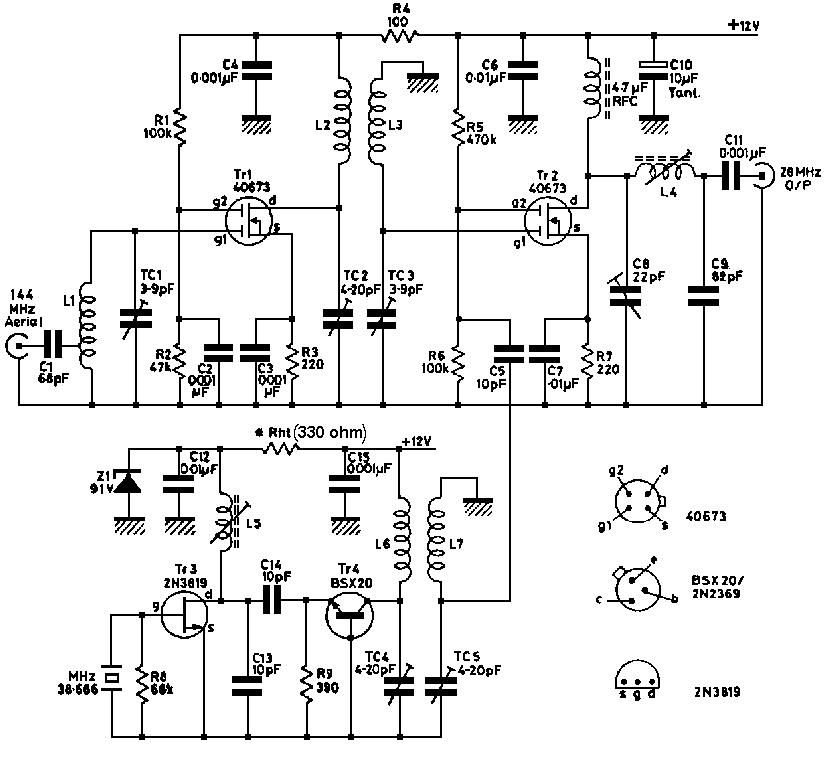
The signal arriving at the aerial is matched into the input of a MOSFET rf. amplifier which magnifies its amplitude by 8 times and passes the larger signal to the mixer. Here the input signal is fed to the most sensitive electrode ( gate 1 ) of another MOSFET, and a signal from the oscillator/multiplier chain is fed to the other control electrode ( gate 2), These are then mixed together in the electron stream of the device emerging at the drain, together with the sum and difference of the two frequencies.
The biasing conditions for the mixer do not allow it to provide much gain but it does amplify the signal by a further two-and-a-half times. The signal selected from those present at the drain is the difference signal, which is 144-116=28MHz This is now matched to a low impedance suitable for feeding via coaxial cable to the receiver, The local oscillator signal is developed from an oscillator running at 38.6666 MHz as a reference, and a multiplier stage which produces multiples of this frequency. Then it selects the tripled frequency at 116MHz and filters it before injection into the mixer.
Circuit Description .
The 144MHz signal enters the input terminal at an impedance of 50 ohm and is coupled via capacitor C1 to a low impedance tapping point on L1. This coilsteps up the voltage in a manner which is proportional to the ratio of input turns to output turns. Similarly, the impedance is transformed up by the square of the turns ratio to provide a suitable match into gate 1 of Tr1. The trimmer TC1 tunes L1 to resonance in the 2-metre amateur band.
Resistors R1 and R2 provide bias at 33% of the supply voltage to the gain control electrode gate 2. Capacitor C2 decouples any variations of this voltage at radio frequencies to maintain constant gain conditions in the stage, Resistor R3 provides a voltage drop from the source/drain current flowing through it, making the source more positive than gate 1, or conversely, making gate 1 more negative than the source, This is the manner in which gate 1 bias is achieved and again this voltage issmoothed at signal frequency by the decoupling action of C3.
The amplified signal appearsat the drain electrode and is develope across L2,this being tuned to resonance by TC2.The coil is closed coupled to L3 and draw. offany signalsthat appear on it at their mutual frequency, other unwanted signals being heavily attenuated trimmer TC3 tunes L3 to resonance at the same frequency as L2 and.TC2, The signal then passes into gate 1 of Tr2 as the impedance of L3/TC3 presents a fairly good match to the gate, Bias for this gate is develop in asimilar fashion to Tr1 by the operation of R7 and C7. The bias for gate 2 of Tr2 is'more critical than for TR1as this device, when acting as a mixer,must be driven well down on its characteristic curve for good mixing to take place. This bias voltage developed by the combination R5 and R6 should normally be 1/11th of the supply rail voltage but its predse value for good mixing is wlely dependent on oscillator drive. For a mass-produced unit such as this one, it is better to bias the gate slightly higher than normal-ie, 1/16th of the suppy voltage---to take account of low gain device, in the osdUator strip and ensure that all units will work fairly well. For the perfectionist, it would be worth frying a 47k resistor for R6 to take full benefit of the low noise figures that can be obtained with twos converter, The rf, choke in the drain circuit allows all the products of mixing to be developed across it whilst the pi circuit C8, C9 and L4 tune out the required difference signal at 28-3OMHz for feeding to the receiver, One of the prindpal purposes of the pi arrangement is to match the signal to the low impedance coaxial output capacitor. Capacitor C11 separates the d.c. connection via RFC and L4 from the output terminal, Supply line components C4, C6 and C10 decouple any r.f. signals leaving the unit and prevent undesirable interaction between the various stages. Resistor R4 aids the decoupling wbilst providing good isolation from large lacal osdllatar signals appearing on it's supply,
The oscillator works due to feedback from thedrain of Tr3 being passed back to the gate by virtue of the internal capacitance of the device, thus maintaining tuned gate/tuned drain oscillation in a similar manner to that developed by Miller for thermionicdevices To start and maintain the oscillation, the resonant circuit foimed by L5, C13 and C14 must be tuned to the same frequency as the crystal.
Resistor R8 provides a d.c path for the gatewithout damping the crystal. at the same time limiting the voltage across it to a reasonable level This ensures that the fet. works over a fairly linear section of its characteristic curve, to reduce the generation of harmonics The components Zl, C12 and Rb' stabilise the oscillator supply voltage to minimise frequency shift due to variations of the supply line voltage. The value of resistor Rh, is dependent on the Id.. of the f.e.t. and may be determined by the expression shown in the components list.
Therefore. in this case use a 330ohm resistor The Id.. can be found by coupling the source of the f.e.t to the gate and connecting the combination to the negative rail of a low voltage supply-say 6V Wire the drain via a 50mA meter to the positive pole of the supply : the Id.. can then be established The multiplier transistor Tr4 operates in the grounded-base mode and is normally non-conducting.
This is because no forward bias is applied to the hase/emitter iunction The transistor requires 0.6V to switch on and thus does not conduct during negativehalf-cycles of the oscillator output signal; only for that proportion of the positive half-cycle which exceeds 0,6V In this manner. only short-duration pulses arrive at the collector and these are transformed into a rough sine wave by the flywheel action of the tuned circuit L6/TC4 The composite waveform contains many multiples of the original or fundomental frequency. but usually the signal of greatest magnitude is that to which the circuit is tuned. The coil L7 extracts the required signal by mutual coupling at a specific frequency. reiecting, to a large extent, those frequencies which are unwanted. The trimmer TC5 tunes L7 to the same multiple frequency as L6/TC4.
In this way the 116MHz signal has an amplitude 5OdB (300 times ) greater than any of the unwanted multiples, providing virtually a pure sine waveform to the mixer and a relatively clean mixing action.
Construction and Layout
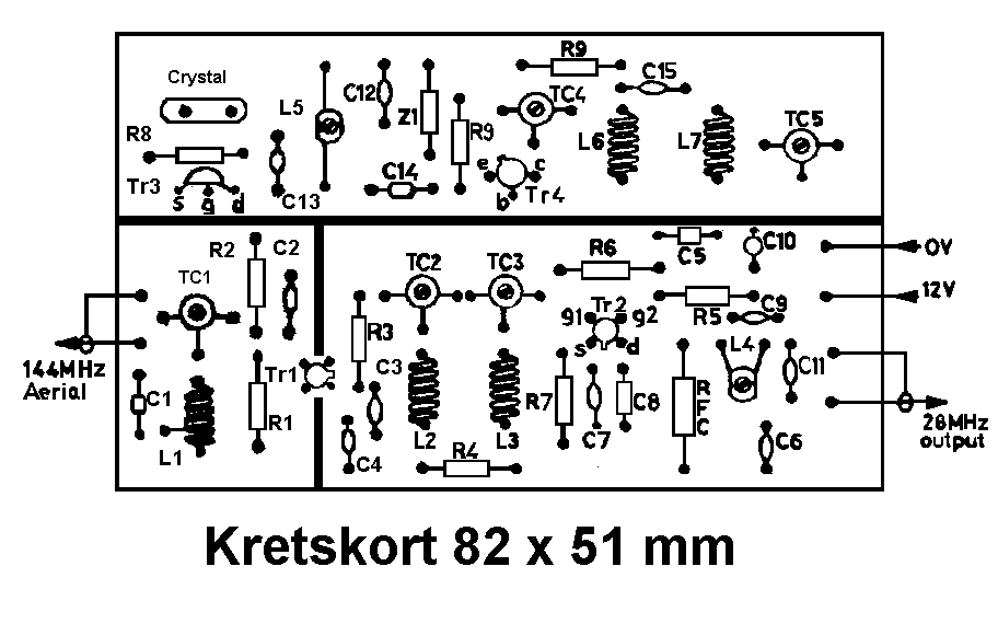
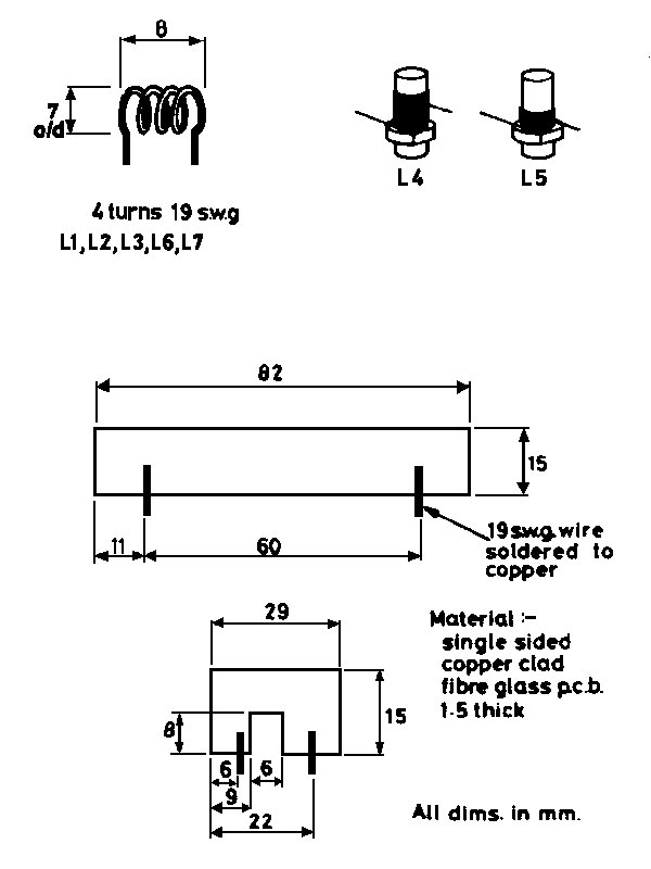
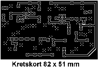
The component layout provided puts the circuit into a small and stable form. Copper-clad chassis techniques could be employed, but would probably result in a reduction in overall performance. The board is easy to assemble and no problemsshould be encountered provided the coils are wound to the specified dimensions and the screens reproduced as shown, The board may be mounted within the cabinet of a receiver, which will tend to reduce stray pick-up at the intermediate frequency of 28-30MHz. No dificulties should arise from internally mounting the unlt unless the local oscillator of the receiver should happen to be poorly screened, and be producing bar. monics which fall within the 2 metre band.
Another method of using the converter is as an out-board unit, connected to the receiver at its aerial socket and to a 12V supply line, In this case it would be ideal if the unit were fitted in a 111.1x60-3x27mm die.cast box, such as the Eddystone EDD 20, or West Hyde "Bopal" 102/103 with suitable coaxialconnectors fitted and a supply input socket,
An internal supply using a PP3 battery could also be utilised if the Zener stabiliser in the oscill ator is changed to a 6V8 type and Rht suitably adjusted in value. The converter would then be completely selfcontained and could be used with valve receivers where an internal 12V supply is not normally available,

Coil Winding Details
Coils L1, L2, L3, L6 and L7 are identical, with the exception of a tap at 11/4 turns on L1. They are all made using a 6.5mm drill as a winding mandrel. All coils can be wound using 19 or 20 s.w.g. tinned copper wire and, with the exception of L1, may be constructed from enamelled wire for appearances sake. The turns are separated evenly until the coils are 9mm (0-3 inches ) long. Coil L4 is wound using 30 s.w.g. enamelled copper wire with a total of 17 turns on a 5mm slug-tuned former , which is then fixed to the board with cyano acrylate adhesive. Enamelled 30 s.w.g. copper is also used for L5, which is wound with 9 turns on a 5mm slug-tuned former and fixed in the same manner. Both the coils are close-wound, the windings being subsequently waxed to aid stability and to hold in place whilst fitting to the board.

Alignment and Operation
Once the unit has been completed and checked for faults, the battery or other supply may be connected and the current measured. This should be in the order of 20mA at 12V If all is well the oscillator can now be adjusted with the core of L5, using a wavemeter to sense when oscillation occurs and to tune for maximum output. At this point, the supply should be switched off and on again to ensure that the oscillator re-starts. If it does not, then detune the coil slightly until instantaneous oscillation occurs at switch-on. Once correct, use a wavemeter to tune L6/TC4 to 116MHz and then tune L7/TC5; return to TC4 and peak, then TC5 again to achieve maximum output, as these coils will tend to detune each other.
Plug the converter into the aerial socket of a receiver and tune the set to 29MHz, now adjust L4 for maximum noise at the speaker. Carefully tune the station receiver from 28 to 30MHz and try to find a signal- If a station is heard or a locally-generated signal is available trimmers TC1, TC2, and TC3 can be peaked for maximum output from the speaker or against a reading on the s-meter (which is usually much more accurate).
The trimmers TC4 and TC5 should now be carefully turned for optimum converter gain. No further adjustments are required and the unit should give you years of satisfactory operation without the need for any further adjustment if a small drop of wax is melted into the coil cores to ensure rigidity.


