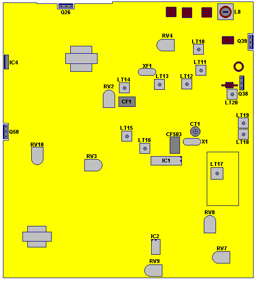
Albrecht AE8000 CB-Radio

Click on parts to view parts description
 CT 1: IF Oscillator 10.240MHz
CT 200: Referenceoscillator 4.5 MHz
RV 2: Squelch
RV 3: S-Meter
RV 4: Power-Meter
RV 8: FM-Modulation
RV 7: AM Modulation
RV 9: ALC
RV 10: 10 Volt Power
AE 8000 Jumpers and Version Settings
For Export or use by authorized radio amateurs the national AE 8000 versions can be
converted to 400 CH in 10 bands which then cover the frequency range 25.165 MHz to
29.655 MHz according to our frequency list.
Because the units are factory pre-aligned for the national CB ranges only, we cannot
confirm full function to all of the frequency ranges. PLL section LT17 and/or TX filters
LT18/19 may need realignment to the desired frequency range.
Restoring AM function in CEPT model (converting to 40/40 CH).
The AM-FM button and the AM display Icon are blocked in this version.
AM/FM button enable: close CON 6b
AM display enable: close CON 7
Channel extension:
open CON 1
Ch 9 button function change close CON 2
Each time when CH9 is kept pressed during switching power on, CH 9 function will be
changed to Band Switch function. Pressing this button will then switch the bands from A
to J . (this will be displayed instead of 09) After the radio has been switched off again,
the original function of CH 9 switch is automatically restored again and the radio works
again on 40 channels.
All these jumpers are clearly marked on the component side of the front panel PCB. For
modification the housing cover must be opened (caution: there are speaker wires
between main board and cover).
CON 1 and 2 are above the filter potentiometer, Con 6b (3 pin jumper, the right position
is 6b) is below the CPU, CON 7 is on the left from the LCD display.
AM power increase to 4 Watts
The power switch is CON 5 on the main board. CON 5 can be found about 5 cm from
the front panel end of main board near J26. Cut the wire connection across CON 5 will
increade AM power to 4 Watts.
RF output tuning:
Semifixed potentiometer RV 10 is used to adjust the power amplifier DC voltage.
Caution: This voltage also supplies the audio amp and the lamps for the display and S-Meter
illumination. Too much voltage may reduce the lifetime of lamps!
New versions have a series resistor in the lamp supply wiring, which can be increased if
necessary ( R 287 on the component side of Front PCB, which is not yet mentioned in
circuit diagram of ALL VERSIONS and CEPT version)


