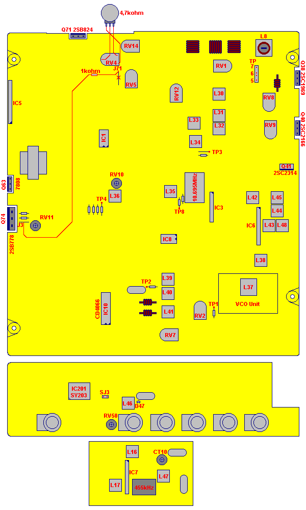
| Reading Point | Condition | Adjustment | Procedure |
|---|
| PLL | ALIGNMENT PROCEDURE | | |
| TP1 | | L37 | 5.1 Volt +/- 50mV on DC VoltMeter |
| TP3 | AM 27.185MHz | L38 | Maximum on Oscilloscope |
| | | |
| OSCILLATOR | ALIGNMENT PROCEDURE | | |
| TP2 | AM 27.185MHz | L39 | 10.6950MHz on Frequency Counter |
| TP2 | USB 27.185MHz | L40 | 10.6925MHz on Frequency Counter |
| TP2 | LSB 27.185MHz | L41 | 10.6975MHz on Frequency Counter |
| IC201 Pin1 | | L46 | 4.500000MHz on Frequency Counter |
| Q102 Base | | CT10 | 10.240MHz on Frequency Counter |
| | RV50 | TX Frequency Set. (CPU-Board) |
| RECEIVER | ALIGNMENT PROCEDURE | | |
| TP8 | USB 27.185MHz | L30 | Maximum on Oscilloscope |
| TP8 | USB 27.185MHz | L31 | Maximum on Oscilloscope |
| TP8 | USB 27.185MHz | L32 | Maximum on Oscilloscope |
| TP8 | USB 27.185MHz | L33 | Maximum on Oscilloscope |
| TP8 | USB 27.185MHz | L34 | Maximum on Oscilloscope |
| TP4 | USB 27.185MHz | L35 | Maximum on Oscilloscope |
| TP4 | USB 27.185MHz | L36 | Maximum on Oscilloscope |
| IC7 Pin1 | FM 27.185MHz | L47 | Maximum on Oscilloscope |
| IC7 Pin1 | FM 27.185MHz | L16 | Maximum on Oscilloscope |
| IC7 Pin7 | FM 27.185MHz | L17 | Maximum on Oscilloscope (FM Discriminator) |
| TRANSMITTER | ALIGNMENT PROCEDURE | | |
| TP5(+) - TP6(-) | Remove CONN 1 | RV9 | 35mA on DC Amperemeter |
| TP5(+) - TP7(-) | Remove CONN 1 | RV8 | 85mA on DC Amperemeter |
| RF Power | TX AM 27.185MHz | L42 | Maximum on RF PowerMeter |
| RF Power | TX AM 27.185MHz | L43 | Maximum on RF PowerMeter |
| RF Power | TX AM 27.185MHz | L44 | Maximum on RF PowerMeter |
| RF Power | TX AM 27.185MHz | L45 | Maximum on RF PowerMeter |
| RF Power | TX AM 27.185MHz | L48 | Maximum on RF PowerMeter |
| RF Power | TX AM 27.185MHz | L8 | Maximum on RF PowerMeter |
| RF Power | TX USB 27.185MHz | RV14 | Set RF Power to 16 Watt |
| RF Power | TX AM 27.185MHz | RV4 | Set RF Power to 10 Watt |
| | RV5 | AM Modulation |
| | RV10 | FM Modulation |
| METER | ALIGNMENT PROCEDURE | | |
| | RV12 | S-Meter Set |
| | RV7 | Modulation-Meter Set |
| | RV1 | RF Power-Meter Set |
| . | ALIGNMENT PROCEDURE | | |
| | RV2 | SQ Set |
| | RV11 | 13.7 Volt Set |
| | | |


