
| Power Supply: 13,8 V | Frequency Counter | DC Voltmeter | Oscilloscope |
| AF VTVM | RF Power Meter | Deviation Meter | Audio Oscillator |
| S/RF-SWR-CAL | S/RF |
| MIC GAIN | Max. |
| Step | Condition | Adjustment | Procedure |
|---|---|---|---|
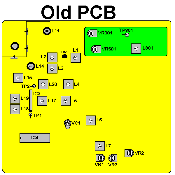
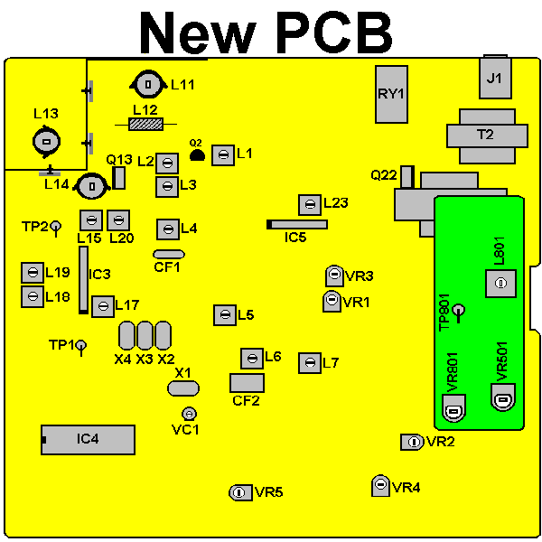
| 1 | CH: 19 BAND: MID POWER: Max. AM, No Mod. | L19 L20 L18 | At first, turn down the coar of L18 to end. Connect Oscilloscope to TP2 (lead of R79). Adjust coils for maximum reading on Oscilloscope |
| 2 | CH: 19, BAND: MID POWER: Max. AM, No Mod. | L20 L15 L14 | Connect RF Power meter to Antenna jack. Adjust coils for maximum reading on RF Power Meter. |
| 3 | CH: 1, BAND: LOW CH: 40, BAND: HIGH POWER: Max. AM, No Mod. | L11 | Adjust L11 for minimum difference between the follow conditions of the set: CH: 1, BAND: LOW CH: 40, BAND: HIGH |
| 4 | CH: 19 BAND: MID POWER: Max. AM, No Mod. | VR3 | Adjust VR3 so that the needle of built-in TX Power Meter point Brank sone of "Sig. 9" |
| 5 | CH: 19 BAND: MID POWER: Min. AM, No Mod. | VR501 | Adjust VR501 so that the RF output power level is over 1.5 V and under 4.0 V in every channel. |
| 6 | CH: 1 BAND: MID POWER: Max. FM | VR801 | Connect Deviation Meter to Ant. jack and AF Oscillator to Mic jack. Set AF Oscillator to 30 mV output. Adjust VR801 for 4 kHz deviation. |
| 7 | CH: 19 BAND: MID POWER: Max. AM, No Mod. | VC1 | Connect Frequency Counter to Ant. jack. Adjust VC1 for 27.185000 +/- 20 Hz on Frequency Counter. |

