![]()
Receiver modification for President George
Varicap Tuned Circuits
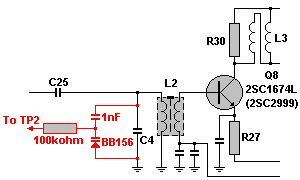 In the first stages of the HF input L2 and C4 is responsible for the
selectivity of the receiver. This is a narrowband filter, and will not cover the hole
26.065 to 28.755 frequency band with full sensitivity.
In the first stages of the HF input L2 and C4 is responsible for the
selectivity of the receiver. This is a narrowband filter, and will not cover the hole
26.065 to 28.755 frequency band with full sensitivity.
To achieve maximum sensitivity for 26.065MHz C4 will increase to 36pF, and for 28.755MHz
C4 will reduce to 29pF. This is possible by a varicapdiode.
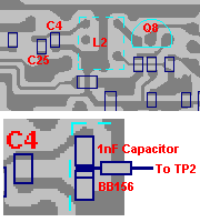
To cover the hole band, replace C4 with 22pF ceramic capacitor and connect the varicap
tuned circuits across C4. Connect 100kohm resistor to TP2.
Set the station to RX AM 27.405 MHz. Connect the DC Voltmeter to TP2 and adjust L405 for
2.5 Volt +/- 0.01 Volt. The VCO-Voltage will then be 4,4Volt@26.065MHz and
1,5Volt@28.755MHz. The BB134 or is 14pF@1,5Volt and 7pF@4,4Volt, and 14pF||22pF=36pF and
7pF||22pF=29pF.
Re-adjust L2 for maximum gain.
| C4 | TP2 |
|---|---|
|
|

Improved receive gain
Quieting of SSB and AM reception and improving gain of incoming signals is a common
request from radio operators.
In the first stages of the HF input 2SC1674 (Q8)
transistor can be found. This transistor is responsible for the amplification of a small
detected signals. A problems exist if the transistor itself is noisy as is such the case
of the 2SC1674 when compared to other low noise packages. Along with the amplification of
the incoming signals is transistor noise. Replacement of this transistor with a higher
gain, lower noise transistor greatly improves the signal to noise ratio of your receiver.
The transistor Q8 operates at VCE= 6Volt and IE= 2,5mA. We will use
an 2SC2999 transistor that has higher gain and lower
noise characteristic. Replace 2SC1674 (Q8) with 2SC2999 (or similar low noise and high
gain transistor) to achieve this improved signal to noise ratio.
Re-adjust L2.
The gain will improved with more than 6dB with the same signal to noise ratio.